Top Tools for the Home Engine Builder
Want to build engines at home like the pros? Here are the tools you’ll need to do the job.
The days of the budget-friendly crate engine have sadly disappeared. Sure, you can still find a fully assembled long-block for less than $3,000, but with cast pistons and rebuilder heads, these are rarely parts a performance engine builder would choose. The alternative is to build the engine yourself. But therein lies the challenge. The actual procedures aren’t that difficult, and the most daunting impediment may be assembling the tools needed to do the job properly.
AI Quick Summary
Author Jeff Smith picks out the essential tools for home engine builders, highlighting the need for quality measurement devices like micrometers and dial bore gauges. Smith suggests investing in tools for accurate assembly and encourages building skills while noting some homemade tool alternatives.
This summary was generated by AI using content from this MotorTrend article
Read Next
0:00 / 0:00
If you’re like most budding engine builders, you already have a solid collection of hand tools and perhaps a few specialty items like a torque wrench, a battery-powered drill, and other such items. But engine assembly is a specific category unto itself that demands significant investments.
We’ll take a look at what it takes for budding engine builders to assemble their first engine. We’ll also point out some nice tools that offer ways to get the job done more quickly and efficiently; you may not be able to afford them right now, but you can put these on your “Futures” list for birthdays or other special occasions—like Tuesdays.
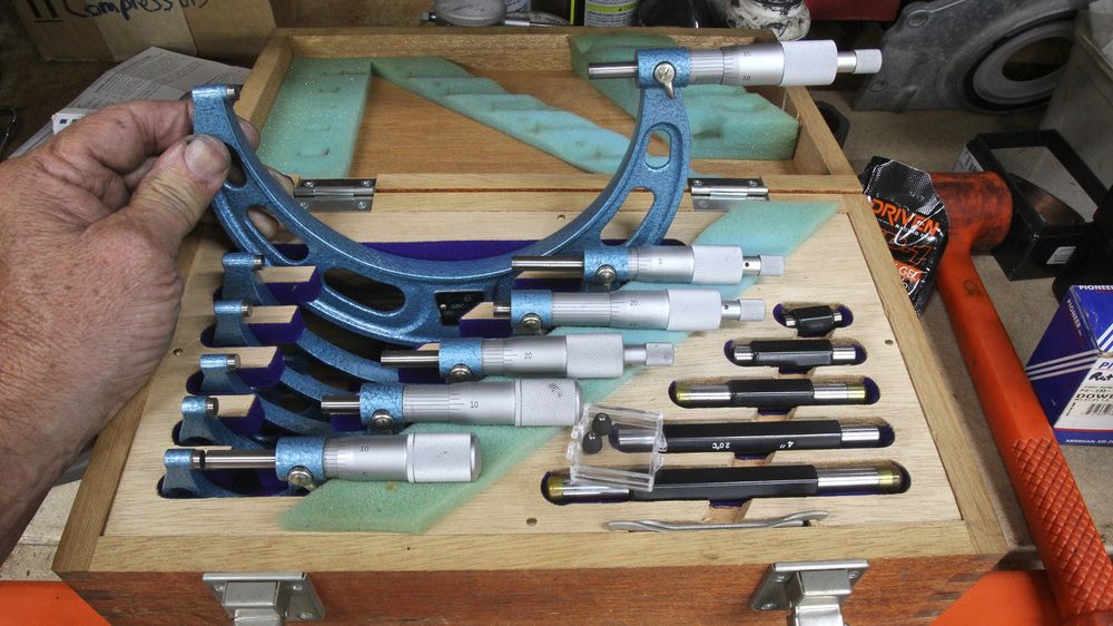
Many years ago, we bought this set of Fowler mics, but we rarely measure anything larger than 4.50 inches. We mainly use the 2.00–3.00 mic for measuring crank journals, so that might be a good place to start.
This story is not intended to be exhaustive. Instead, this overview will point you in a direction where you can choose the tools you think you will need first. Then, as resources permit, you can enhance your tool lineup to include other tricks of the trade. While most implements in this story are universal, several are specific, aimed at either the small-block Chevy or LS engines, so check the application of the tools beforehand to make sure these implements will play nicely with the engine you plan to assemble.
Perhaps the first question to address is whether there are multiple engine family builds in your future. This doesn’t mean you plan to become a professional engine builder. Maybe your goal is just to be the neighborhood gearhead who likes to assemble engines and will do so for friends and acquaintances. This is an important question because it will point you toward how much you’re willing to invest in these tools. This can be a sizable amount, but it will also pay off in terms of the money you will save over decades building engines.
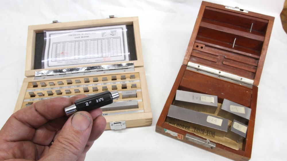
When doing any measurement, first establish if the mic is accurate by testing it against a standard. These blocks came from a retired machinist. Each block is accurate at 68 degrees to 3 to 5 millionths of an inch (0.000003 to 0.000005 inch).
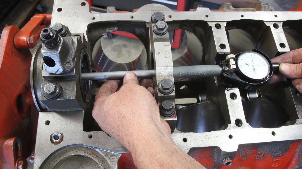
The most critical and time-consuming process of all engine-building techniques is establishing accurate rod and main bearing clearances. This is because this process requires not only significant capital investment in specialty measuring devices but also expertise in reading and setting up a micrometer and dial bore gauge. While quality micrometers have come down in price dramatically over the past couple of decades, good mics and dial bore gauges are still expensive.
For those willing to make the commitment, the only outside micrometers to consider are the ones accurate to 0.0001 inch. This is one tenth of 0.001 inch. You don’t want to settle for the cheapest price here. In our search, we found a mic set on Temu, where you can buy the ultra-cheap Chinese version of stuff. This is exactly what you should avoid. Invest your hard-earned dollars in quality brands like Mitutoyo, Starrett, or perhaps Fowler. If you talk to builders and machinists who use their micrometers every day, you’ll find they will be brand loyal, but they will also tell you the truth.
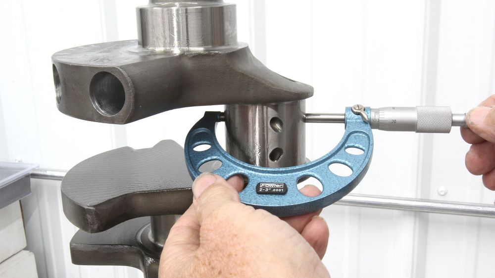
It’s best to establish a procedure when measuring journal diameters with a micrometer and then always perform the job the same way. It’s also best to take multiple measurements on each journal for runout and accuracy.
Combined with a micrometer is a dial bore gauge that will measure the inside diameter of a main bearing bore or a connecting rod bearing. These tools rely on a micrometer to establish the outside diameter of the main journal, for example, then the dial bore gauge measures the inside diameter with the indicated difference on the gauge as the actual bearing clearance. Again, quality is the key here because there are dozens of cheap tools screaming for your attention. If you buy a quality tool like a Mitutoyo, the numbers you generate will be reliable as long as you follow the proper procedures.
Here’s where we will take a controversial stand by saying that relying on a piece of green wax string to establish your bearing clearance is foolhardy at best. Why would you risk a $4,000-plus engine on a measurement from a squished length of wax string? If you are an entry-level builder and can’t afford a set of micrometers and a dial bore gauge, then take your parts to a professional and pay them to do the measurements or have a trustworthy friend do the job. A friend will likely offer to measure your stuff for you while teaching you how to perform the process yourself. There’s much to learn.
This is the Mitutoyo dial bore gauge we’ve used for years. We treat it with respect and store it carefully. It often reveals what we don’t want to know, but at least we know the numbers are accurate. Good tools always make the job much easier.
Moving on, among our most-used precision measurement tools is a dial indicator mounted to a magnetic base. This tool can be used in multiple applications, such as crank endplay, roller cam endplay, measuring lifter movement for degreeing cams, and more. Get a dial gauge with at least 1 inch of movement accurate to 0.001 inch.
While we’re milling around the rotating assembly, most high-performance rod bolts like those from ARP will offer a rod bolt stretch spec along with a torque figure. Rod bolt stretch is a far more accurate way to establish the proper clamp load on the rod cap. We learned the hard way that if your torque wrench is not calibrated, the rod bolt torque can be inaccurate, and this can lead to an under-torqued rod bolt that will fail when the rod nut loosens. You will know instantly if that happens.
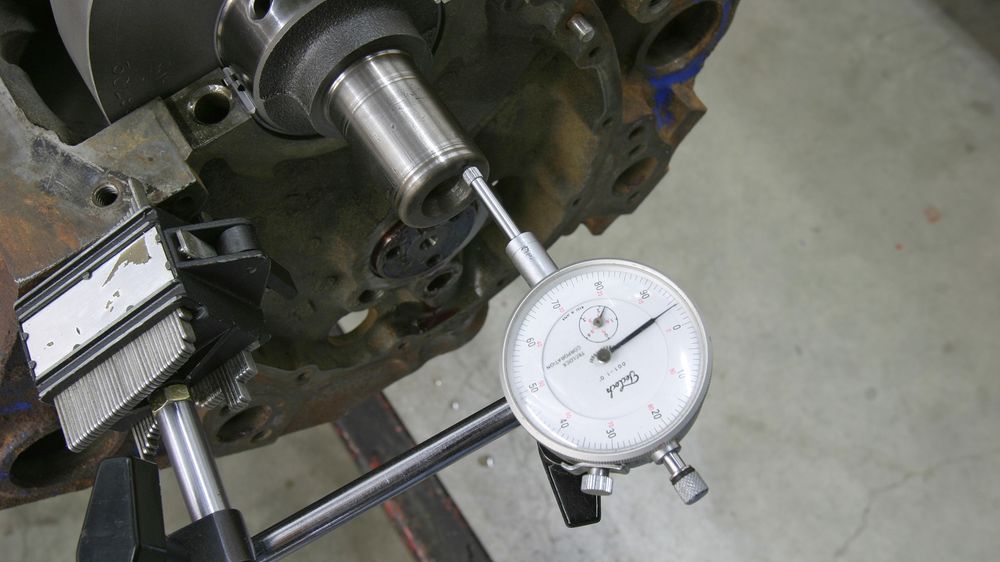
There are multiple engine-building operations that require a dial indicator mounted on a magnetic base. Crank and cam endplay, cam degreeing, and piston-to-valve clearance are a few of the major uses for this tool. Look for an indicator that offers at least 1 inch of travel with accuracy to 0.001 inch.
Speaking of torque, newer engines like LS, Gen III Hemis, and Ford Mod motors all employ a technique called torque-angle for main cap and head bolts. Although you can buy an expensive digital angle torque wrench, there are several very affordable manual torque-angle gauges that will do the job quickly and easily.
Setting ring end gap is also something you might like to do. Our experience is that standard replacement rings offer rather wide clearances to err on the conservative (wider) side of the spec. That’s why most engine builders prefer to file their own rings to set the end gaps where they want them. This can be accomplished with an inexpensive manual ring grinder. These are great for entry-level engine builders, but just know this will burn up some time in the process. Electric ring filers do the job very quickly but are also expensive and aimed mainly at professional engine builders.
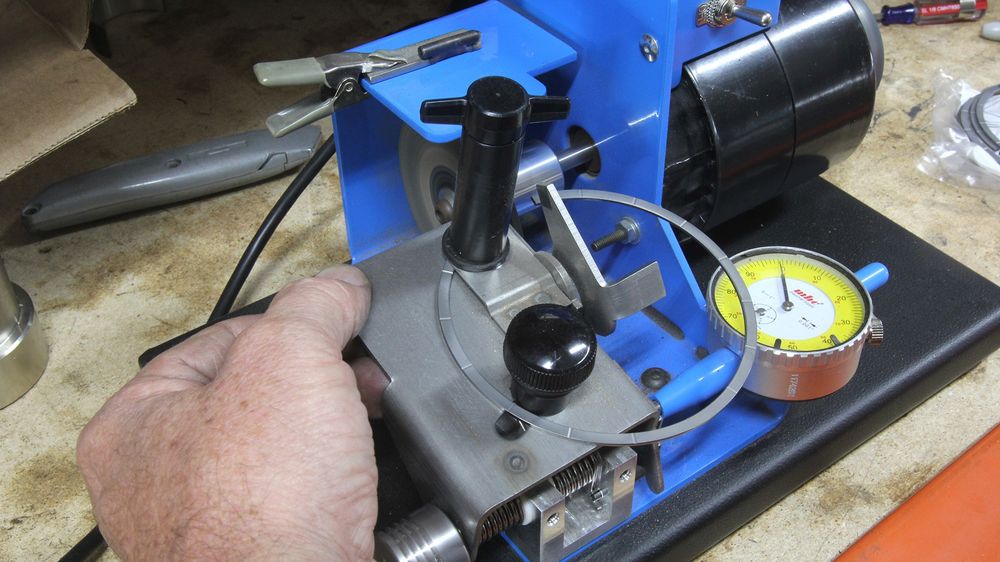
Manual ring grinders work great, but it does take time to set 16 individual rings. This electric ring filer from Summit can do the job in one quarter of the time it takes with the manual tool. When using the manual tool, always turn the handle counter-clockwise.
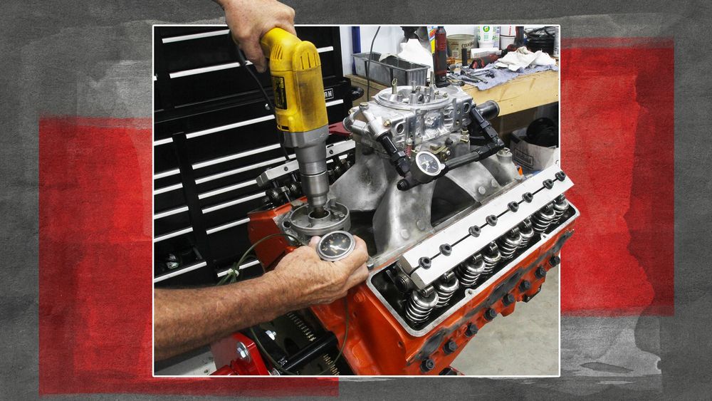
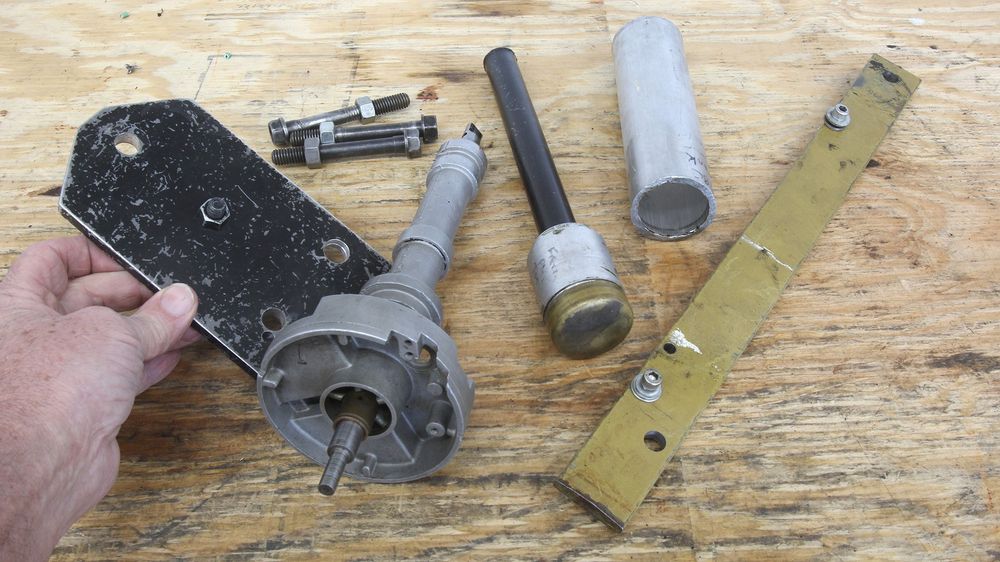
With the rotating system covered, we can now move into the valvetrain area. Performance engine building means using a camshaft with more lift and duration. This also demands knowing where the cam is located relative to top dead center (TDC). The only way to know this is to degree the camshaft. Among the tools you will need is the correct lifter, a dial indicator to measure lifter travel, and a degree wheel mounted on the crankshaft with a pointer reference. Several companies offer cam degreeing kits that include most of the items you will need, but of all the tools besides the degree wheel itself, the crank snout tool is also very important.
Once the engine is assembled, it’s also an excellent plan to pressure lube the lubrication system to push oil to all the internal components. This is easy with older engines with distributors, because you can use an electric drill to spin a distributor shaft to spin the oil pump. With later-model engines using crank-mounted oil pumps, this is a bit more complicated process. Several years ago, we built a homemade pre-luber using a 2.5-gallon plastic pail with a small-block Chevy oil pump bolted to the lid. We plumbed the pump’s pressure outlet to the engine and extended the oil pickup into the bottom of the bucket. Using an electric drill motor to drive the oil pump, we also fabricated a return from the oil pan back to the bucket. While homemade, it works great to this day. If this sounds like too much work, Summit offers a pressurized aluminum container that uses compressed air to push oil into the engine. It’s not overly expensive, but it requires draining the oil pan several times and refilling the container to fully push oil through the entire engine. On some LS engines, we’ve never been able to pressure lube oil up through the pushrods. The lifters are too restrictive, and the oil never gets to the top of the rockers until the engine starts and runs.
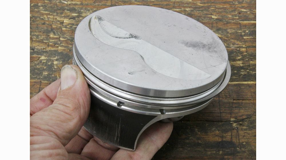
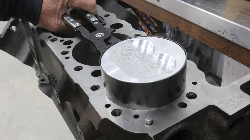
You can buy an inexpensive universal piston ring squaring tool, but before they were available, we used an old flap-top piston with a ring in the second groove. We invert the piston into the bore, and it pushes the ring down about 3/8-inch from the deck and squares the ring against the top of the piston. Then we can quickly check ring end gap.
One last recommendation would be to also keep a separate notebook for each engine you build that covers not only clearances but also cam degreeing information, whether the cam is advance or retarded, and other info like piston-to-valve clearance. A list of all the part numbers would also be helpful for reference after several years have passed and your memory turns fuzzy.
Engine building is a great way to test your mechanical skills and abilities. Plus, there’s that great feeling of accomplishment when the engine fires and runs after a complete rebuild. You won’t know what that feels like until you’ve experienced it for yourself. It makes all the work worthwhile.
More Tools for the Home Engine Builder
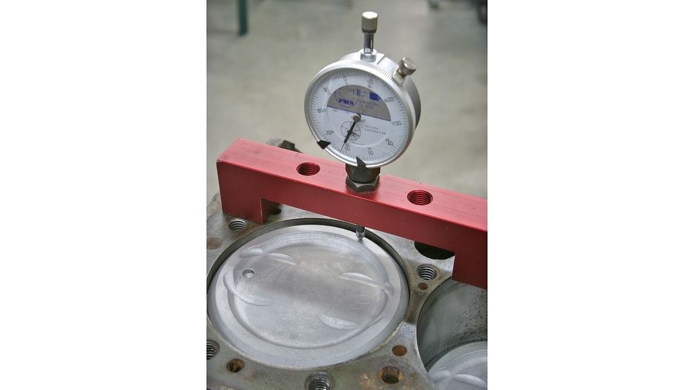
Deck bridges are a great way to measure piston-to-deck height. An accurate piston height above or below the deck is important for accurate compression ratio calculations.
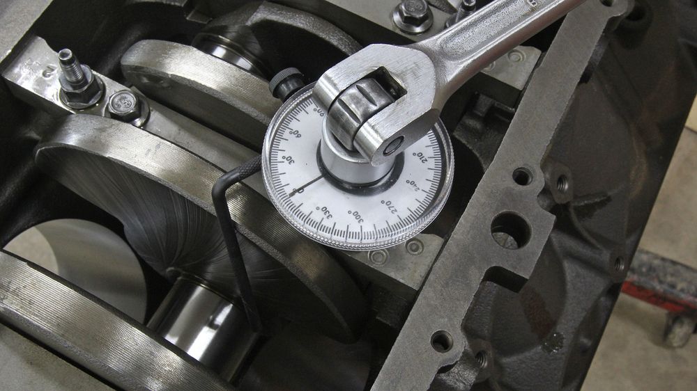
Many modern engines now require fasteners using a torque-angle spec. A slight initial torque is set followed by a number of degrees of rotation of the fastener. For example, an LS main cap bolt will require an initial torque of 15 ft-lb followed by 53 degrees of additional tightening. This is an inexpensive torque-angle gauge that will do the job nicely.
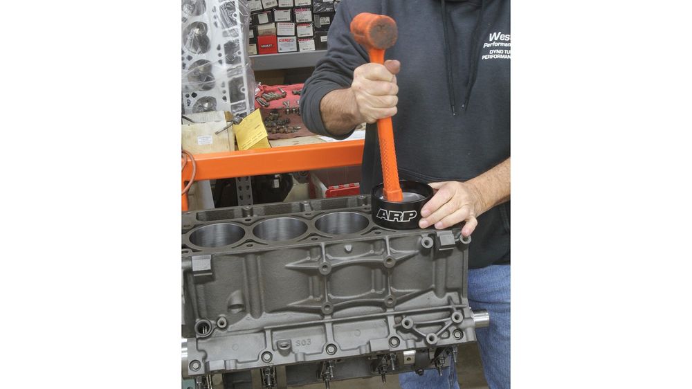
Tapered ring compressors make installing pistons and rings very easy. Their only drawback is they are only useful with a specific bore size like 4.030 inches, for example.
If you anticipate building multiple engines with different bore sizes, it would be beneficial to seek out a universal clamp-style ring compressor with multiple band sizes to accommodate the different bore diameters. These tools require a bit of skill to use, but with experience they do an excellent job.
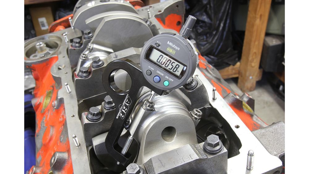
The only proper way to set a rod bolt clamp load is with a rod bolt stretch figure. This is the only way to properly establish the load for the most highly stressed fastener in the engine. This happens to be an ARP digital rod bolt stretch gauge, but there are affordable analog gauges that do a great job.
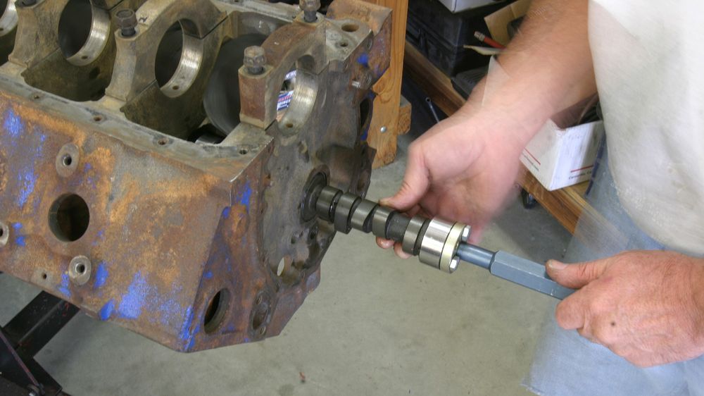
You can install a cam in almost any V-8 engine with a long bolt screwed to the cam face, but we prefer to use a dedicated cam install handle. This tool is a little hard to see in this photo, but the handle is about 8 inches long for additional leverage.
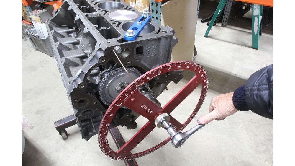
The only way to know for sure that the camshaft is installed correctly in the engine is to degree the cam. A large pro version degree wheel is not necessary, but the larger wheels are generally more accurate.
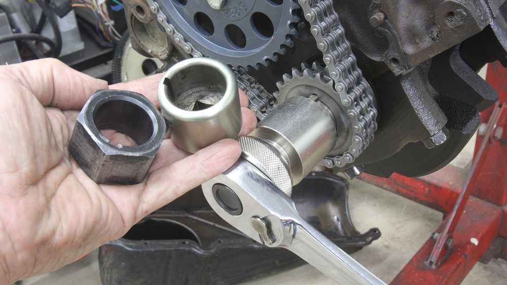
We’ve learned that using a crank-turning socket allows mounting the degree wheel with a separate fixture that makes life much easier. A crank socket prevents errant movement and allows you to do the job quickly and accurately. The black tool is a crank-turning nut for a small-block Chevy, and the gold tool is also a crank-turning socket used for turning the engine when a degree wheel is not present.
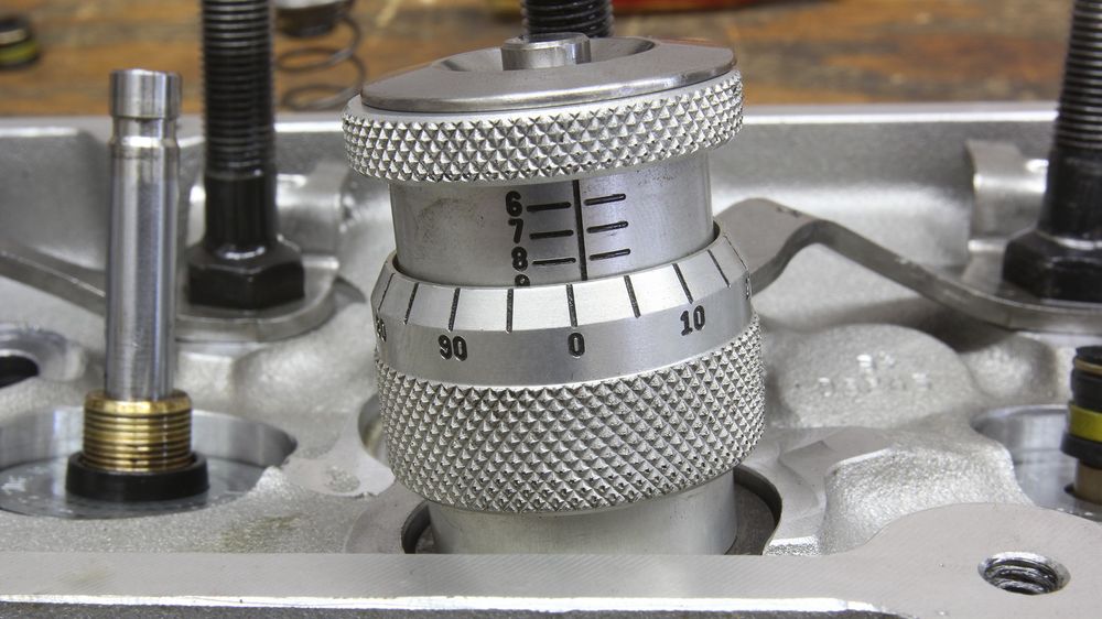
If you want to assemble your own valvetrain, a height mic like this one will quickly measure the installed height of the valve retainer. It’s a handy little tool.
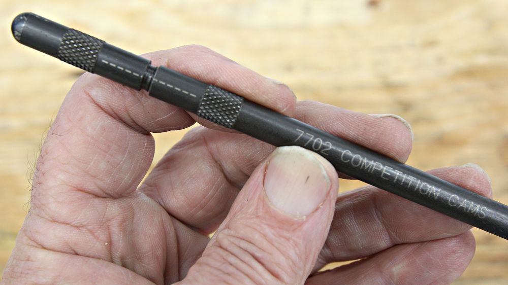
A quick way to establish pushrod length is to use a tool like this one from COMP. The pushrod expands in 0.050-inch turns. Place the lobe on its base circle, slide in the lifter and the adjustable pushrod, and adjust the pushrod to the correct length to properly position the rocker tip over the valve. These come in various lengths, so you will need to know the rough length of the pushrod in order to select the correct tool.
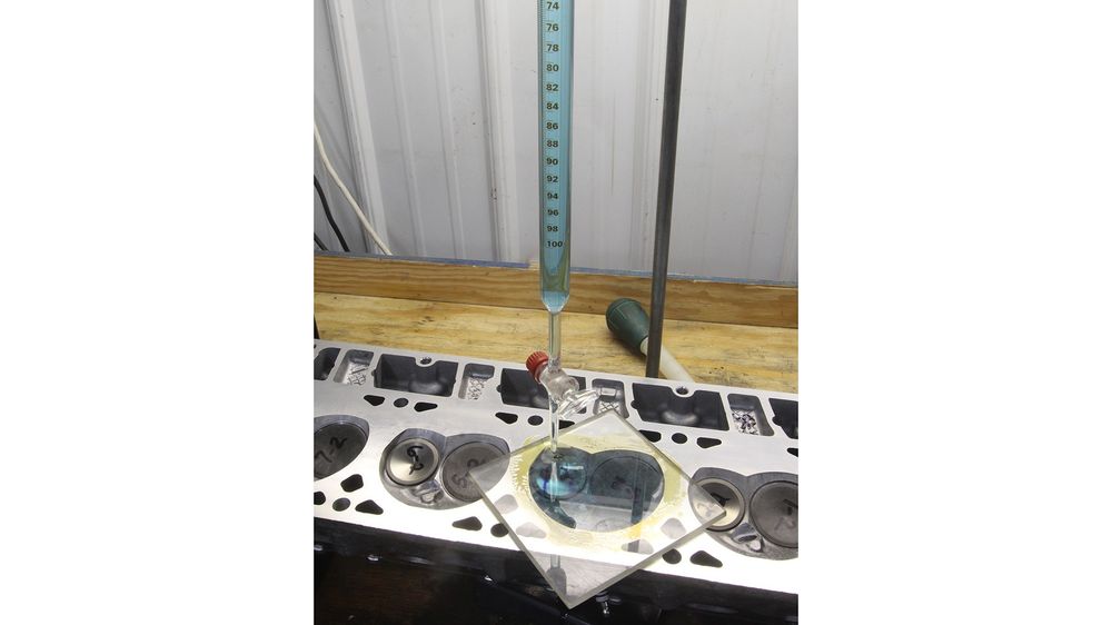
The only way to accurately compute your engine’s compression ratio is to measure the volume of the combustion chamber. To do this requires a 100cc graduated burette. We use colored rubbing alcohol for the fluid because it’s easy to clean after taking the measurements. Note that this process can also measure the volume of the piston in the bore.
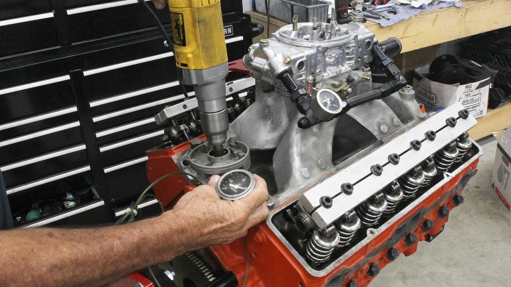
After final assembly, it’s a good idea to pressure-lube the engine by spinning the oil pump with an electric drill motor. We like to use this old HEI distributor where the shaft is turned down to fit a drill motor. For modern engines with crank-mounted oil pumps, we built a homemade pre-luber with a small-block Chevy oil pump mounted to the lid on a 2.5-gallon bucket with the outlet connected to the main oil passage for an LS, Gen III Hemi, or a Ford Mod motor. This will push oil through all the passages to pre-lube the entire engine before first firing.
Checking Accuracy
Once you have built a few engines and have established some competency in reading precision instruments, these tools need to be periodically calibrated. This may call for standards, and owning them will save time. We purchased some used steel standards that came from the aviation industry and are accurate to 0.000003 inch at 68 degrees F. These can be used to verify the accuracy of not only outside micrometers but also items like dial indicators, dial bore gauges, and other tools.
Tool List
The tools listed her are from Summit Racing and the internet and represent various examples. There are literally thousands more to chose from but at least you can get an idea of what’s available.
Homemade Tools
This is a short list of tools we’ve made ourselves over the years to accomplish certain tasks at a time when these tools didn’t exist. Most of these are now available and not expensive, but we find we still prefer our homemade versions.
- Pressure-lube tool using an old distributor
- Iron plate drilled for valve cover bolts—place for magnetic base on alum heads
- Aluminum plate for piston stop to set TDC with the heads off
- Piston ring squaring tool
- Thick wall aluminum pipe to press on crank gears
- Freeze plug driver
In Summary
These are just some of the tools that we’ve used over many years of building engines, including the small-block HEI distributor for pre-lubing, the iron plate for mounting a magnetic base dial indicator, the short length of thick wall aluminum tubing for mounting a crank gear, and the piston stop plate.
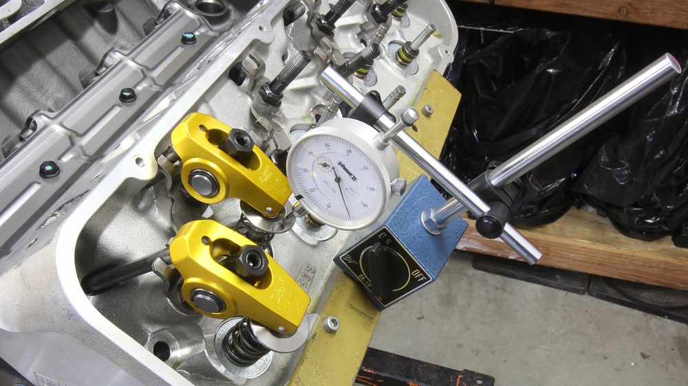
This simple length of steel plate bolts to the head with valve cover bolts offering a convenient position for a magnetic dial indicator base on aluminum heads.